Most physical quantities - temperature, light, pressure, position - are continuous. The analog-to-digital converter turns them into discrete values the microcontroller can process, with precision limited by the resolution and the chosen reference voltage.
1Lab objectives
- Understanding successive-approximation conversion
- Calculating resolution, the quantum, and quantization error
- Correctly choosing the reference voltage and the prescaler
- Reading a potentiometer and an analog sensor
- Converting the digital value back into the measured physical quantity
- Reducing noise through averaging
2Materials needed
- 1 Arduino Uno
- 1 Breadboard
- 1 10 kΩ potentiometer
- 1 Photoresistor (LDR)
- 1 10 kΩ resistor
- 1 LM35 sensor (optional)
- 6 Jumper wires
3The conversion principle
The ATmega328P uses a SAR converter (Successive Approximation Register). The principle resembles weighing with weights: each bit is tested in turn, starting with the most significant, and kept if the internally generated voltage does not exceed the input.
4Converter parameters
| Parameter | Value on the ATmega328P | Meaning |
|---|---|---|
| Resolution | 10 bits | 1024 distinct levels (0...1023) |
| Channels | 6 (A0...A5) | multiplexed - a single converter switched between inputs |
| Default V_ref | 5 V (AVCC) | can be switched to an internal 1.1 V or to an external AREF |
| Conversion time | 13 ADC cycles | ≈ 104 µs at prescaler 128 |
| First conversion | 25 cycles | includes initializing the analog circuitry |
| Recommended frequency | 50-200 kHz | above 200 kHz the effective resolution drops below 10 bits |
| Recommended source impedance | under 10 kΩ | above this value, the sampling capacitor does not charge fully |
ADC = V_in · 1024 / 5, and one unit represents
5 / 1024 = 4.88 mV - this is the quantum, or LSB.5Conversion simulator
Adjust the input voltage and watch the digital value, the quantum, and the quantization error. The chart shows the converter's staircase characteristic against the ideal line. Change the prescaler and watch the warning when you leave the recommended range.
6Choosing the reference voltage
Precision depends directly on V_ref: the narrower the range, the finer each step. A sensor that produces 0-1 V, read with V_ref = 5 V, uses only 205 of the 1024 available levels - more than 80% of the resolution is wasted.
| V_ref | Quantum (LSB) | Selecting it in Arduino | Suited for |
|---|---|---|---|
| 5.0 V (AVCC) | 4.88 mV | analogReference(DEFAULT) | potentiometers, 0-5 V dividers |
| 1.1 V (internal) | 1.07 mV | analogReference(INTERNAL) | LM35, thermocouples, small signals |
| external (AREF) | V_AREF / 1024 | analogReference(EXTERNAL) | external precision reference |
analogReference(EXTERNAL), the voltage must be applied to the AREF pin
before the first reading. Otherwise the internal reference can short against the
external one and destroy the microcontroller.analogReference() is unreliable -
it should be discarded.7The ADC registers
Change the bits and watch the resulting values. The default configuration corresponds to channel A0, AVCC reference, converter enabled, prescaler 128.


| Bit | Register | Role |
|---|---|---|
REFS1:REFS0 | ADMUX | 00 = external AREF · 01 = AVCC (5 V) · 11 = internal 1.1 V |
ADLAR | ADMUX | left alignment - useful for a fast 8-bit read |
MUX3:MUX0 | ADMUX | selects the channel: 0000 = A0 ... 0101 = A5 |
ADEN | ADCSRA | turns on the ADC module |
ADSC | ADCSRA | triggers a conversion; returns to 0 when it finishes |
ADIE | ADCSRA | enables the interrupt on conversion completion |
ADPS2:ADPS0 | ADCSRA | prescaler: 111 = 128 → 16 MHz / 128 = 125 kHz |
ADCL and
ADCH. ADCL must be read first: the hardware locks the register until ADCH
is also read. Reversing the order can produce values combined from different conversions. In
C, using the ADC variable does this automatically and correctly.8Simulator: the conversion sequence
Follow step by step what happens at the register level during a manually triggered conversion, from selecting the channel to reading the result.
while (ADCSRA & (1 << ADSC))
loop blocks the processor for 104 µs. For applications that cannot afford that, ADIE
is enabled and ADC_vect is handled: the conversion runs in the background, and the
ISR picks up the result.9Wiring diagrams
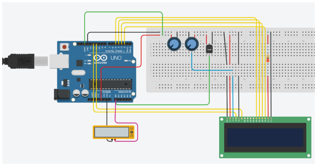
10Reducing noise
ADC readings fluctuate even with a perfectly stable input, due to internal and external electrical noise. There are three common ways to improve this:
| Method | Effect | Cost |
|---|---|---|
| Averaging over N samples | noise drops by √N | time: N × 104 µs |
| Exponential filter | continuous smoothing, no array | a single multiplication per reading |
| 100 nF capacitor on the input | filters high-frequency noise | one component; slows the response |
average = average + (fresh - average) / 8; - equivalent to averaging over roughly
8 samples, but with no array and no float. Dividing by a power of 2 compiles into
a simple bit shift.11Source code
Reading the potentiometer
const uint8_t POT_PIN = A0;

void setup() {
  DDRB = 0x3F;                                  // pins 8...13: the 6-LED bar
}

void loop() {
  uint16_t raw = analogRead(POT_PIN);           // 0...1023
  float voltage = raw * 5.0 / 1024.0;           // convert back to volts
  uint8_t percent = map(raw, 0, 1023, 0, 100);

  // We do not have the serial monitor yet (lab 6). We show the result in
  // binary, on the 6 most significant bits: shifting by 4 leaves 0...63.
  PORTB = raw >> 4;

  delay(200);
}
Direct register configuration
void adcInit() {
  ADMUX  = (1 << REFS0);                                  // AVCC reference (5 V)
  ADCSRA = (1 << ADEN)                                    // turn on the converter
         | (1 << ADPS2) | (1 << ADPS1) | (1 << ADPS0);    // prescaler 128 -> 125 kHz
}

uint16_t adcRead(uint8_t channel) {
  ADMUX = (ADMUX & 0xF0) | (channel & 0x0F);   // select the channel, keep the reference
  ADCSRA |= (1 << ADSC);                       // start the conversion
  while (ADCSRA & (1 << ADSC));                // wait for it to finish
  return ADC;                                  // read the 10-bit result
}

void setup() {
  DDRB = 0x3F;             // 6-LED bar on pins 8...13
  adcInit();
  adcRead(0);              // the first conversion takes longer - discard it
}

void loop() {
  PORTB = adcRead(0) >> 4;   // the 6 most significant bits, on the bar
  delay(100);
}
Averaging and filtering
const uint8_t PIN = A0;
const uint8_t N   = 16;          // a power of 2 -> division becomes a shift

uint16_t averagedRead() {
  uint32_t sum = 0;
  for (uint8_t i = 0; i < N; i++) sum += analogRead(PIN);
  return sum / N;
}

void setup() {
  DDRB = 0x3F;                   // bar on pins 8...13 = the RAW value
  DDRD |= 0b11111100;            // pins 2...7        = the FILTERED value
}

void loop() {
  static uint16_t filtered = 0;

  uint16_t raw      = analogRead(PIN);
  uint16_t averaged = averagedRead();

  // exponential filter, integers only
  filtered = filtered + ((int16_t)(averaged - filtered) / 8);

  // Compare the two bars: the raw one jitters, the filtered one moves smoothly.
  PORTB = raw      >> 4;
  PORTD = (PORTD & 0x03) | ((filtered >> 4) << 2);

  delay(50);
}
Measuring temperature with the LM35
The LM35 sensor produces 10 mV for every degree Celsius. At 25 °C the output voltage is 250 mV, i.e. only 51 of the 1024 available levels - a classic case where the internal 1.1 V reference significantly improves precision.
const uint8_t SENSOR_PIN = A1;

void setup() {
  DDRB = 0x3F;                   // thermometer bar on pins 8...13
  DDRD |= (1 << PD7);            // alarm LED on pin 7
  analogReference(INTERNAL);     // internal 1.1 V reference
  delay(10);
  analogRead(SENSOR_PIN);        // discard the first reading after the change
}

void loop() {
  uint32_t sum = 0;
  for (uint8_t i = 0; i < 16; i++) { sum += analogRead(SENSOR_PIN); delay(2); }
  uint16_t raw = sum / 16;

  // integer version: temperature in tenths of a degree
  // (1100 mV / 1024 steps, and the LM35 gives 10 mV per degree -> mV = tenths of a degree)
  int16_t tempTenths = (int32_t)raw * 1100 / 1024;
  int16_t tempC = tempTenths / 10;

  // bar thermometer: one LED for every 10 degrees
  uint8_t nrLeds = tempC / 10;
  if (nrLeds > 6) nrLeds = 6;
  PORTB = (1 << nrLeds) - 1;

  if (tempC > 40) PORTD |=  (1 << PD7);
  else            PORTD &= ~(1 << PD7);

  delay(500);
}
Driving an LED based on ambient light
const uint8_t LDR_PIN = A0;
const uint8_t LED_PIN = 9;        // PWM pin
const uint16_t LOWER_THRESHOLD = 300;
const uint16_t UPPER_THRESHOLD = 700;

void setup() {
  pinMode(LED_PIN, OUTPUT);
  DDRB |= 0b00111101;             // status bar (except pin 9, used by PWM)
}

void loop() {
  uint16_t light = analogRead(LDR_PIN);

  // the darker it is, the brighter the LED shines
  uint8_t duty = map(constrain(light, LOWER_THRESHOLD, UPPER_THRESHOLD),
                     LOWER_THRESHOLD, UPPER_THRESHOLD, 255, 0);
  analogWrite(LED_PIN, duty);

  delay(100);
}
constrainThe map function does not clamp
the result to the output range: if the input exceeds the thresholds, the returned value falls
outside 0-255 and produces unexpected behavior when converted to uint8_t.12Interactive circuit
The analog-to-digital converter turns a voltage into an integer between 0 and 1023. Move the sliders below and watch, at the same time: the applied voltage, the raw value read, and that same number shown in binary on the LED bar.
PORTB = raw >> 2; - the high bits are lost
and the bar becomes chaotic.(1 << n) - 1 lights up exactly the first
n LEDs - the same mask construction from the second lab.13Work tasks
- Connect the potentiometer and print the raw value, the voltage, and the percentage over serial.
- Determine the quantum experimentally: turn the potentiometer slowly and observe the minimum step of variation.
- Build the circuit with the photoresistor and the 10 kΩ resistor; display the light level.
- Drive an LED's brightness through PWM, inversely proportional to the ambient light.
- Implement averaging over 16 samples and compare the stability with the version without averaging.
- Compare averaging with the exponential filter: which one responds faster to a sudden change?
- Switch the reference to the internal 1.1 V and observe how the value changes for the same voltage.
- Rewrite the reading using the ADMUX and ADCSRA registers directly, without
analogRead().
14Extended application
Further extension: implement reading through interrupt (
ADC_vect) and
measure how much time the processor gains compared to the busy-wait version.