Timer modules are hardware counters that run independently of the processor. They generate precise intervals, measure durations, and produce PWM signals - without blocking the program with delay().
1Lab objectives
- Understanding the role of the prescaler and computing the counting frequency
- Configuring CTC mode to generate a precise time base
- Using the compare-match interrupt for periodic execution
- Generating PWM signals and controlling the duty cycle
- Replacing
delay()with non-blocking timing
2Materials needed
- 1 Arduino Uno
- 1 Breadboard
- 2 LEDs + 220 Ω resistors
- 1 10 kΩ potentiometer
- 1 Passive buzzer (optional)
- 6 Jumper wires
3Theoretical background
How it works
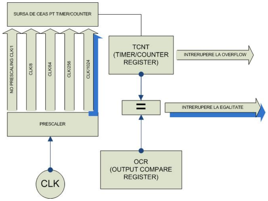
A timer is a counter that increases by 1 with every clock pulse it receives. When it reaches its maximum value (255 for 8 bits, 65,535 for 16 bits), it resets and sets an overflow flag. Being implemented in hardware, it counts in parallel with program execution.
Timers available on the ATmega328P
| Timer | Resolution | PWM pins | Used internally by |
|---|---|---|---|
| Timer0 | 8 bits | D5, D6 | millis(), delay() - avoid modifying |
| Timer1 | 16 bits | D9, D10 | the Servo library |
| Timer2 | 8 bits | D3, D11 | tone() |
The prescaler
The 16 MHz clock is too fast for long intervals: a 16-bit timer would fill up in just 4.1 ms. The prescaler divides the frequency before it reaches the counter:
| Prescaler N | Counting frequency | Duration of 1 increment | Time to overflow (16 bits) |
|---|---|---|---|
| 1 | 16 MHz | 62.5 ns | 4.10 ms |
| 8 | 2 MHz | 0.5 µs | 32.8 ms |
| 64 | 250 kHz | 4 µs | 262 ms |
| 256 | 62.5 kHz | 16 µs | 1.05 s |
| 1024 | 15.625 kHz | 64 µs | 4.19 s |
Operating modes
4Interactive timer calculator
Change the parameters and watch how the period and frequency change. The chart shows the counter climbing to the compare value and the resulting signal at the pin.
5Generating a PWM signal
PWM (Pulse Width Modulation) produces a variable average voltage by switching rapidly between 0 and 5 V. The ratio between the "on" time and the total period is called the duty cycle. An LED driven this way appears to change brightness, and a motor changes speed.
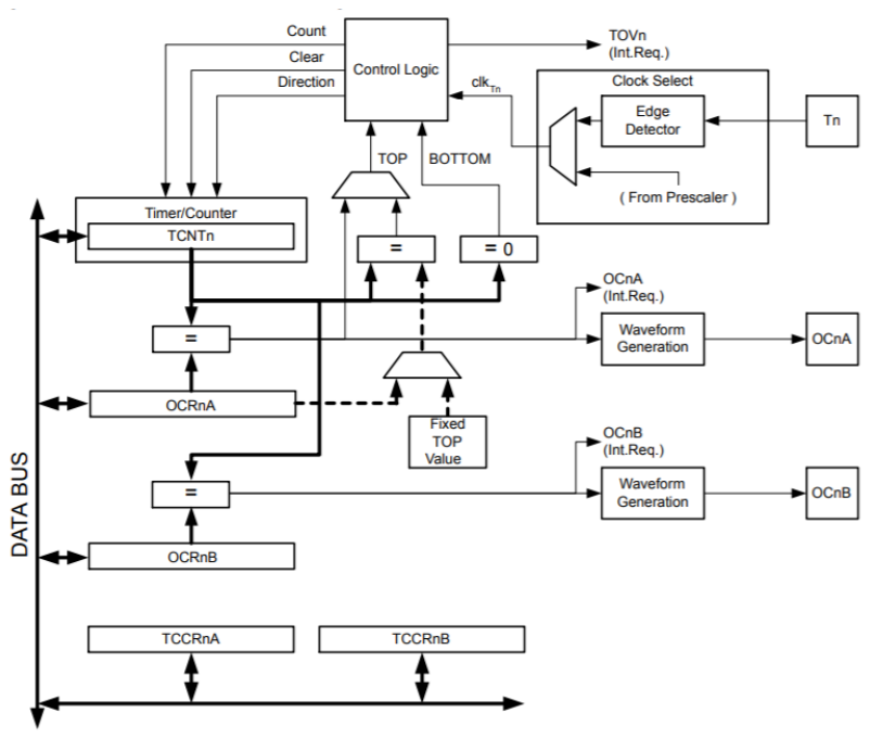


TCCR0A → TCCR1A) along with the
counter's range. Timer1 is preferred because it does not interfere with millis().PWM at the register level - what analogWrite() does
The analogWrite() function hides the configuration of three registers. Written
explicitly, the same operation looks like this - and becomes fully controllable: you can choose the
frequency, resolution, and polarity, things impossible through the library.
void pwmInit() {
  DDRB |= (1 << PB1);              // pin 9 (OC1A) as output

  // COM1A1 = 1, COM1A0 = 0  -> non-inverted output: HIGH at start, LOW at compare
  TCCR1A |= (1 << COM1A1);
  TCCR1A &= ~(1 << COM1A0);

  // WGM13:WGM10 = 0101  -> Fast PWM, 8-bit (TOP = 255)
  TCCR1A |=  (1 << WGM10);
  TCCR1A &= ~(1 << WGM11);
  TCCR1B |=  (1 << WGM12);
  TCCR1B &= ~(1 << WGM13);

  // prescaler 64 -> f_PWM = 16 MHz / (64 * 256) = 976 Hz
  TCCR1B &= ~((1 << CS12) | (1 << CS11) | (1 << CS10));   // clear the field
  TCCR1B |=   (1 << CS11) | (1 << CS10);                   // write 011
}

void pwmSet(uint8_t duty) {
  OCR1A = duty;                    // 0 = always off, 255 = almost always on
}

void setup() {
  pwmInit();
  pwmSet(128);                     // 50% - equivalent to analogWrite(9, 128)
}

void loop() { }
|= - the previous bits would remain active too. First the
entire field is cleared with &= ~(...), then the desired value is written. This is
the standard idiom for any multi-bit field, explained at length in
Laboratory 1B.analogWrite() forces 490 Hz on pins
9 and 10. For driving a motor, this frequency falls in the audible band and produces an annoying
whine. Through direct configuration you can go above 20 kHz, past the threshold of hearing - a
frequent requirement in practice, impossible to meet with the library.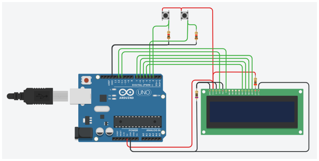
Porting a timer configuration
| Step | AVR / ATmega328P | STM32 | ESP32 |
|---|---|---|---|
| Enabling the clock | implicit | RCC->APB1ENR |= TIM2EN | handled by the SDK |
| Prescaler | TCCR1B, bits CS12:CS10 | TIMx->PSC (direct value) | divider in LEDC configuration |
| Compare value | OCR1A | TIMx->CCR1 | ledc_set_duty() |
| Period / TOP | ICR1 or fixed | TIMx->ARR | resolution in bits |
| Enabling the interrupt | TIMSK1 |= (1<<OCIE1A) | TIMx->DIER |= CC1IE | registered callback |
6Source code
A 1-second time base in CTC mode
volatile bool secondElapsed = false;

ISR(TIMER1_COMPA_vect) {      // runs exactly once every second
  secondElapsed = true;
  PORTB ^= (1 << PB5);        // toggle the LED on pin 13
}

void setup() {
  DDRB |= (1 << PB5);

  cli();                      // stop interrupts while configuring
  TCCR1A = 0;                 // clear the registers
  TCCR1B = 0;
  TCNT1  = 0;                 // reset the counter

  OCR1A = 62499;              // (16,000,000 / 256) - 1 = 1 second
  TCCR1B |= (1 << WGM12);     // CTC mode
  TCCR1B |= (1 << CS12);      // prescaler 256
  TIMSK1 |= (1 << OCIE1A);    // enable the compare interrupt
  sei();                      // re-enable interrupts

  DDRB |= (1 << PB4);         // pin 12: witness for the main loop
}

void loop() {
  if (secondElapsed) {
    secondElapsed = false;
    PORTB ^= (1 << PB4);      // proof that the loop received the event
  }
}
Non-blocking timing - the alternative to delay()
delay() stops the program completely. With millis() you can run several
activities with different periods, in parallel:
const uint8_t LED_1 = 8, LED_2 = 9;
unsigned long last1 = 0, last2 = 0;
const unsigned long PERIOD_1 = 250;   // ms
const unsigned long PERIOD_2 = 1000;  // ms

void setup() {
  pinMode(LED_1, OUTPUT);
  pinMode(LED_2, OUTPUT);
}

void loop() {
  unsigned long now = millis();

  if (now - last1 >= PERIOD_1) {
    last1 = now;
    digitalWrite(LED_1, !digitalRead(LED_1));
  }

  if (now - last2 >= PERIOD_2) {
    last2 = now;
    digitalWrite(LED_2, !digitalRead(LED_2));
  }

  // the loop stays free for other tasks
}
PWM brightness control
Here the duty cycle is driven directly from the program, through a ramp. In the fifth lab you will replace it with the value read from a potentiometer, through the analog-to-digital converter.
const uint8_t LED_PIN = 9;    // PWM pin (Timer1)

void setup() {
  pinMode(LED_PIN, OUTPUT);
}

void loop() {
  // ramps up: the LED fades in smoothly
  for (uint16_t duty = 0; duty <= 255; duty += 5) {
    analogWrite(LED_PIN, duty);
    delay(25);
  }

  // ramps down: the LED fades out smoothly
  for (uint16_t duty = 255; duty > 0; duty -= 5) {
    analogWrite(LED_PIN, duty);
    delay(25);
  }
}duty/255 × 5 V.7Interactive circuit
A timer is a counter that runs on its own. The circuits below show you both of its uses: generating a PWM signal (where you can see the wave and the duty cycle) and measuring an exact interval in CTC mode. Change the prescaler in the registers and watch how the frequency changes.
CS11 to CS12
(prescaler 256) and watch the frequency shown under the wave: it drops by a factor of 32, and
the LED starts to flicker visibly.8Work tasks
- Configure Timer1 in CTC mode to generate an interrupt every second and check the accuracy against a stopwatch over 60 seconds.
- Calculate and check the OCR1A values for periods of 0.5 s, 2 s, and 5 s. What happens at 5 s with prescaler 256?
- Write a program that blinks two LEDs with different periods (250 ms and 1 s), without using
delay(). - Drive an LED's brightness through PWM, with the duty cycle set by a potentiometer.
- Measure the PWM signal's frequency on pin 9 and compare it with the theoretical value of 490 Hz.
- Create a "breathing" effect: the LED's brightness rises and falls smoothly, continuously.
9Extended application
millis()).
Add a button on INT0 for start/stop and one on INT1 for reset.