The last lab combines everything studied so far into complete applications: reading from sensors, driving power actuators, wireless communication, and distance measurement. Each application uses at least three of the previously studied modules.
1Lab objectives
- Integrating the studied peripherals into a working application
- Building a weather station with data display
- Driving a DC motor with adjustable speed and direction
- Sending data between two boards through a radio module
- Measuring distance with an ultrasonic sensor and compensating for temperature
- Structuring a complex program as a state machine
2Materials needed
- 2 Arduino Uno boards
- 1 DHT11 / DHT22 sensor
- 1 DC motor + L298N H-bridge
- 2 nRF24L01 modules
- 1 HC-SR04 sensor
- 1 10 kΩ potentiometer
- 1 External 7-12 V supply
- 2 10 µF capacitors
3Application 1 - Weather station
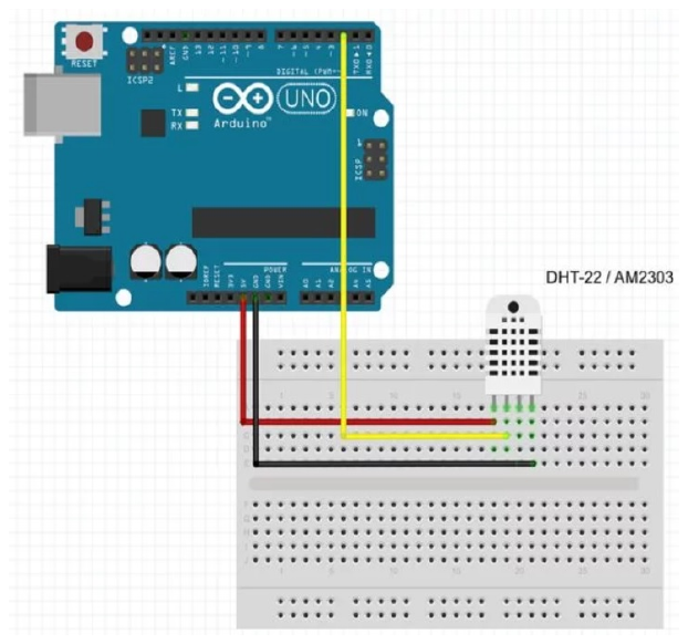
The DHT sensor measures temperature and humidity, sending the data through its own protocol, over a single wire. The timings are very strict (on the order of microseconds), which is why a dedicated library is used.
| Parameter | DHT11 | DHT22 |
|---|---|---|
| Temperature range | 0...50 °C | −40...80 °C |
| Temperature accuracy | ±2 °C | ±0.5 °C |
| Humidity range | 20...90% | 0...100% |
| Resolution | 1 °C / 1% | 0.1 °C / 0.1% |
| Minimum interval between readings | 1 s | 2 s |
| Supply | 3.3-5.5 V | 3.3-6 V |
NaN or the previous value, cached internally. Always
check with isnan() before using the result.
#include <DHT.h>

#define DHT_PIN  7
#define DHT_TYPE DHT11

DHT sensor(DHT_PIN, DHT_TYPE);

unsigned long lastReading = 0;
const unsigned long INTERVAL = 2000;   // respects the minimum interval

float tMin = 999, tMax = -999;         // extreme values since power-on

void setup() {
  Serial.begin(9600);
  sensor.begin();
  Serial.println("Weather station started");
}

void loop() {
  if (millis() - lastReading < INTERVAL) return;   // non-blocking timing
  lastReading = millis();

  float humidity    = sensor.readHumidity();
  float temperature = sensor.readTemperature();

  if (isnan(humidity) || isnan(temperature)) {     // MANDATORY check
    Serial.println("Error reading the sensor!");
    return;
  }

  if (temperature < tMin) tMin = temperature;
  if (temperature > tMax) tMax = temperature;

  float heatIndex = sensor.computeHeatIndex(temperature, humidity, false);

  Serial.print("T = ");        Serial.print(temperature, 1);
  Serial.print(" C   RH = ");  Serial.print(humidity, 1);
  Serial.print(" %   feels like = "); Serial.print(heatIndex, 1);
  Serial.print(" C   [min ");  Serial.print(tMin, 1);
  Serial.print(" / max ");     Serial.print(tMax, 1);
  Serial.println("]");
}
4Application 2 - DC motor control
A motor cannot be powered directly from a microcontroller pin: it draws hundreds of milliamps, while a pin delivers at most 40 mA. An H-bridge is used, which allows both speed control through PWM and reversing the direction of rotation.
| IN1 | IN2 | ENA (PWM) | Effect |
|---|---|---|---|
| 0 | 0 | any | stopped - free spinning (coast) |
| 1 | 0 | 0...255 | forward rotation, speed set by PWM |
| 0 | 1 | 0...255 | reverse rotation |
| 1 | 1 | any | active braking (shorting the terminals) |
5Speed simulator
Adjust the duty cycle and watch the average voltage applied to the motor, as well as the resulting waveform. Compare the displayed value with the minimum starting threshold you will determine experimentally.
const uint8_t IN1 = 4, IN2 = 5, ENA = 9;   // ENA must be a PWM pin
const uint8_t POT_PIN = A0;
const uint8_t MIN_DUTY = 60;               // below this the motor does not start

void setDirection(bool forward) {
  digitalWrite(IN1, forward ? HIGH : LOW);
  digitalWrite(IN2, forward ? LOW  : HIGH);
}

void stopMotor() {
  digitalWrite(IN1, LOW);
  digitalWrite(IN2, LOW);
  analogWrite(ENA, 0);
}

void setup() {
  pinMode(IN1, OUTPUT);
  pinMode(IN2, OUTPUT);
  pinMode(ENA, OUTPUT);
  Serial.begin(9600);
  stopMotor();
}

void loop() {
  uint16_t raw = analogRead(POT_PIN);

  // dead zone in the middle: below 490 backward, above 530 forward, in between stopped
  if (raw < 490) {
    setDirection(false);
    uint8_t duty = map(raw, 489, 0, MIN_DUTY, 255);
    analogWrite(ENA, duty);
    Serial.print("BACKWARD duty="); Serial.println(duty);
  }
  else if (raw > 530) {
    setDirection(true);
    uint8_t duty = map(raw, 531, 1023, MIN_DUTY, 255);
    analogWrite(ENA, duty);
    Serial.print("FORWARD  duty="); Serial.println(duty);
  }
  else {
    stopMotor();
    Serial.println("STOPPED");
  }

  delay(100);
}
6Application 3 - Radio communication
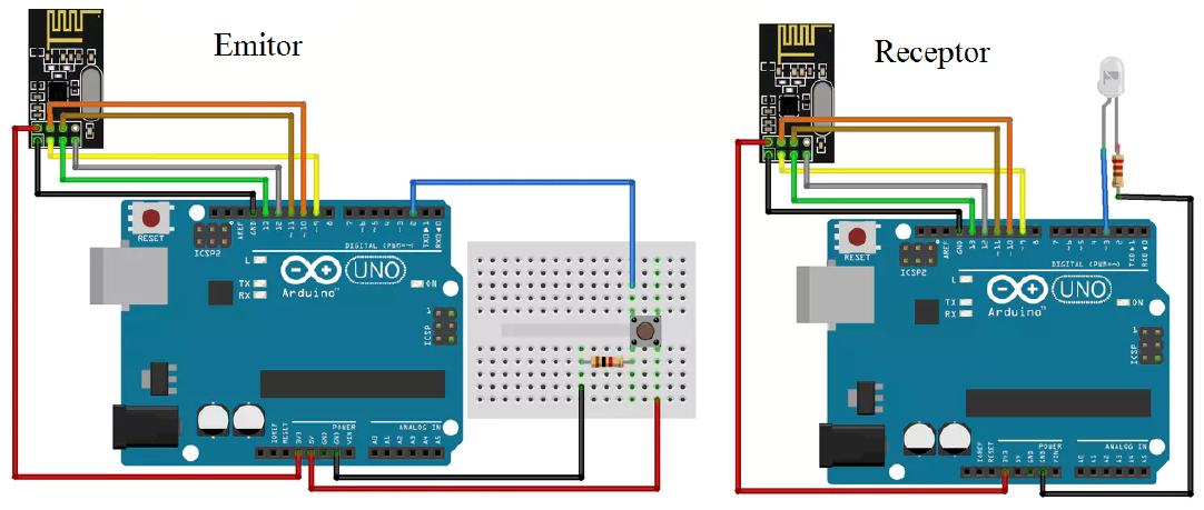
The nRF24L01 module operates in the 2.4 GHz band and communicates with the microcontroller over the SPI bus. It allows bidirectional links over tens of meters and automatically acknowledges received packets.
| nRF24L01 pin | Arduino Uno | Role |
|---|---|---|
| VCC | 3.3 V | power - not 5 V! |
| GND | GND | ground |
| CE | D9 | enable transmit/receive |
| CSN | D10 | SPI select (Slave Select) |
| SCK | D13 | SPI clock |
| MOSI | D11 | data to the module |
| MISO | D12 | data from the module |
#include <SPI.h>
#include <RF24.h>

RF24 radio(9, 10);                        // CE, CSN
const byte address[6] = "NODE1";

struct Packet {                           // the structure MUST BE IDENTICAL on both boards
  uint16_t counter;
  int16_t  temperature;                   // in tenths of a degree, as an integer
  bool     button;
};

Packet data = {0, 0, false};

void setup() {
  Serial.begin(9600);
  pinMode(2, INPUT_PULLUP);

  radio.begin();
  radio.openWritingPipe(address);
  radio.setPALevel(RF24_PA_LOW);          // low power for bench testing
  radio.setDataRate(RF24_250KBPS);        // low speed -> longer range
  radio.stopListening();                  // transmit mode
}

void loop() {
  data.counter++;
  data.temperature = (int16_t)(analogRead(A0) * 0.489);   // example
  data.button = !digitalRead(2);

  bool sent = radio.write(&data, sizeof(data));

  Serial.print("Packet ");  Serial.print(data.counter);
  Serial.println(sent ? " - acknowledged" : " - FAILED");

  delay(500);
}
#include <SPI.h>
#include <RF24.h>

RF24 radio(9, 10);
const byte address[6] = "NODE1";

struct Packet {
  uint16_t counter;
  int16_t  temperature;
  bool     button;
};

Packet data;
uint16_t lastCounter = 0;

void setup() {
  Serial.begin(9600);
  pinMode(3, OUTPUT);                     // LED on another pin: D9-D13 are used by SPI

  radio.begin();
  radio.openReadingPipe(0, address);
  radio.setPALevel(RF24_PA_LOW);
  radio.setDataRate(RF24_250KBPS);
  radio.startListening();                 // receive mode
}

void loop() {
  if (radio.available()) {
    radio.read(&data, sizeof(data));

    digitalWrite(3, data.button);

    // detecting lost packets
    if (data.counter != lastCounter + 1 && lastCounter != 0) {
      Serial.print("!! lost ");
      Serial.print(data.counter - lastCounter - 1);
      Serial.println(" packets");
    }
    lastCounter = data.counter;

    Serial.print("Packet #"); Serial.print(data.counter);
    Serial.print("  T = ");   Serial.print(data.temperature / 10.0, 1);
    Serial.print(" C  button = "); Serial.println(data.button ? "pressed" : "released");
  }
}
7Application 4 - Distance measurement
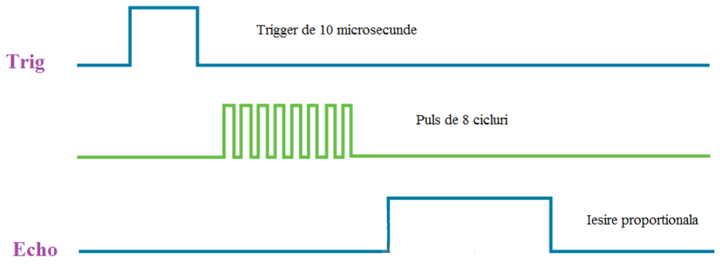
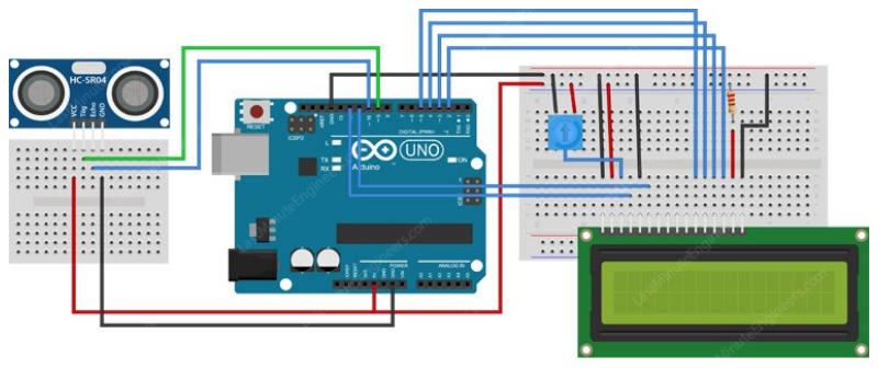
The HC-SR04 sensor emits a 40 kHz ultrasonic pulse and measures the time until the echo returns. Knowing the speed of sound, the distance to the obstacle is calculated.
| Parameter | Value | Notes |
|---|---|---|
| Measurement range | 2 cm ... 4 m | under 2 cm the echo overlaps the emission |
| Accuracy | ±3 mm | under ideal conditions, flat perpendicular surface |
| Measurement angle | ~15° | angled objects can reflect the echo elsewhere |
| TRIG pulse duration | 10 µs | minimum needed to trigger |
| Maximum reading frequency | ~20 Hz | waits for residual echoes to die out |
8Distance calculator
Change the echo duration and the air temperature. Notice the difference
between the exact formula and the simplified one (t/58) - at large distances and
extreme temperatures, the error becomes significant.
const uint8_t TRIG_PIN = 9;
const uint8_t ECHO_PIN = 10;

float speedOfSound(float tempC) {
  return (331.3 + 0.606 * tempC) / 10000.0;   // cm/us
}

float measureDistance(float tempC) {
  digitalWrite(TRIG_PIN, LOW);
  delayMicroseconds(2);
  digitalWrite(TRIG_PIN, HIGH);
  delayMicroseconds(10);                       // the trigger pulse
  digitalWrite(TRIG_PIN, LOW);

  unsigned long duration = pulseIn(ECHO_PIN, HIGH, 30000UL);   // 30 ms limit

  if (duration == 0) return -1.0;              // no echo

  return (duration * speedOfSound(tempC)) / 2.0;  // round trip -> divide by 2
}

void setup() {
  Serial.begin(9600);
  pinMode(TRIG_PIN, OUTPUT);
  pinMode(ECHO_PIN, INPUT);
  pinMode(3, OUTPUT);
}

void loop() {
  float d = measureDistance(20.0);

  if (d < 0) {
    Serial.println("No echo - object too far");
    digitalWrite(3, LOW);
  } else {
    Serial.print("Distance = "); Serial.print(d, 1); Serial.println(" cm");
    digitalWrite(3, d < 20.0);                 // warning under 20 cm
  }

  delay(100);                                   // avoid interference between readings
}
9Integrating the applications
A program that does several things at once cannot use delay(). The recommended
structure combines non-blocking timing with a state machine:
| Module | Period | Method |
|---|---|---|
| Reading the DHT sensor | 2000 ms | non-blocking millis() |
| Distance measurement | 100 ms | non-blocking millis() |
| Motor control | every iteration | directly in loop() |
| Stop button | immediate | interrupt (Lab 3) |
| Radio transmission | 500 ms | non-blocking millis() |
/* The four tasks are the functions written in the applications above.
   They are left empty here, so only the skeleton is clearly visible: */
void readDistance()    { /* application 4 */ }
void readTemperature() { /* application 1 */ }
void sendTelemetry()   { /* application 3 */ }
void updateMotor()     { /* application 2 */ }
void stopMotor()       { /* stops the motor's PWM */ }

unsigned long tDHT = 0, tDist = 0, tRadio = 0;
const unsigned long P_DHT = 2000, P_DIST = 100, P_RADIO = 500;

volatile bool emergencyStop = false;

void stopButton() { emergencyStop = true; }     // a very short ISR

void setup() {
  attachInterrupt(digitalPinToInterrupt(2), stopButton, FALLING);
}

void loop() {
  unsigned long now = millis();

  if (emergencyStop) {                            // has the highest priority
    stopMotor();
    return;
  }

  if (now - tDist >= P_DIST) {
    tDist = now;
    readDistance();
  }

  if (now - tDHT >= P_DHT) {
    tDHT = now;
    readTemperature();
  }

  if (now - tRadio >= P_RADIO) {
    tRadio = now;
    sendTelemetry();
  }

  updateMotor();                          // on every iteration
}
10Simulator: a state machine
An obstacle-avoiding robot cannot be written with delay(): it
would go blind exactly when it needs the sensor. Watch how the state machine solves the
problem, switching between states based on distance and time.
loop()
iteration the sensor is read and the state is re-evaluated. There is never a moment when the
robot "cannot see". With delay(600) instead of the BACKWARD state, the robot
would be completely blind for 0.6 seconds.11Interactive circuit
The last two circuits put together everything you have learned: reading a sensor, making a decision, driving an output, and running several tasks in parallel, without blocking the program.
delay() that would be impossible - a one-second
pause would also stop the fast blink. The millis() pattern is the foundation of
any serious microcontroller program.12Work tasks
- Build the weather station and print the temperature, humidity, and heat index over serial.
- Add tracking of the minimum and maximum values since power-on.
- Wire the H-bridge and drive the motor with variable speed and direction from the potentiometer.
- Determine experimentally the minimum duty cycle at which the motor starts turning.
- Measure the current drawn by the motor at different PWM values and correlate it with the speed.
- Set up the radio link between two boards and transmit the weather station's data.
- Detect and display lost packets, using the counter in the structure.
- Implement distance measurement with temperature compensation from the DHT sensor.
- Combine two applications: the distance sensor stops the motor when it detects an obstacle.
- Rewrite a
delay()-based program as a state machine and compare the responsiveness.
13Final project
- two motors driven through an H-bridge, with speed set by PWM (Lab 4)
- an HC-SR04 sensor for obstacle detection (Lab 5, Lab 7)
- a start/emergency-stop button handled through an interrupt (Lab 3)
- status LEDs driven through direct register access (Lab 2)
- telemetry sent over serial or radio (Lab 6, Lab 7)
- a state-machine structure, with no
delay()anywhere in the main loop
Document the project with the circuit diagram, commented code, and a table of test results: stopping distance as a function of speed, for at least three different PWM values.