Interrupts let the microcontroller react immediately to external events, without wasting time constantly checking the state of pins. They are the mechanism that makes the difference between a system that misses events and one that responds with a guarantee.
1Lab objectives
- Understanding the difference between polling and interrupts
- Configuring the external interrupts INT0 and INT1 through
EICRAandEIMSK - Correctly writing a handling routine (ISR)
- Using the
volatilequalifier and understanding why - Measuring the response latency of both approaches
2Materials needed
- 1 Arduino Uno
- 1 Breadboard
- 2 Buttons
- 2 LEDs + 220 Ω resistors
- 6 Jumper wires
3Why interrupts are needed
In a typical program, checking a button happens inside loop(). If the loop also
contains other operations that take time - an LCD update, an ADC conversion, a
delay() - the event can be missed entirely.
loop() that contains
delay(200) checks the button only 5 times per second. A short, 80 ms press has
roughly a 60% chance of falling entirely inside a pause - and of being lost without a trace.Interrupts solve the problem at the hardware level: when the event occurs, normal execution is suspended immediately, the handling routine runs, then the program resumes exactly where it left off.
4The handling mechanism
- The event occurs (an edge on a pin, a timer overflow, an ADC conversion finishing, etc.)
- The corresponding interrupt flag is set automatically
- If interrupts are enabled globally (
sei()) and locally, the processor finishes the current instruction - The return address is saved on the stack, and global interrupts are disabled
- Execution jumps to the address in the interrupt vector table
- The ISR runs; at
reti()the context is restored and interrupts are re-enabled
5Polling vs. interrupt
Press the button (or click directly on the chart) to generate an external event. Increase the duration of the CPU load and watch how latency grows in the polling variant, while the interrupt responds instantly, regardless of load.
| Criterion | Polling | Interrupt |
|---|---|---|
| Typical latency | the duration of one loop iteration | under 5 µs |
| Worst-case latency | the duration of the entire loop | the duration of the longest active ISR |
| Processor load | continuous, even with no events | only when an event occurs |
| Code complexity | simple | requires volatile and care around
critical sections |
| Suited for | slow signals, periodic checks | short, rare, time-critical events |
6Interrupt sources on the ATmega328P
| Source | Arduino pin | AVR pin | ISR vector | Notes |
|---|---|---|---|---|
| INT0 | D2 | PD2 | INT0_vect | configurable edge |
| INT1 | D3 | PD3 | INT1_vect | configurable edge |
| PCINT0...7 | D8-D13 | port B | PCINT0_vect | any change, grouped by port |
| PCINT8...14 | A0-A5 | port C | PCINT1_vect | any change |
| PCINT16...23 | D0-D7 | port D | PCINT2_vect | any change |
| Timer1 compare A | - | - | TIMER1_COMPA_vect | see Laboratory 4 |
| ADC complete | - | - | ADC_vect | see Laboratory 5 |
| USART receive | - | - | USART_RX_vect | see Laboratory 6 |
7Configuring the registers
| ISC01 | ISC00 | INT0 trigger | Arduino equivalent | Use |
|---|---|---|---|---|
| 0 | 0 | LOW level (as long as the pin is 0) | LOW | waking from sleep; keeps re-triggering |
| 0 | 1 | any level change | CHANGE | encoders, counting both edges |
| 1 | 0 | falling edge (1 → 0) | FALLING | buttons with pull-up |
| 1 | 1 | rising edge (0 → 1) | RISING | buttons with pull-down, sensors active on HIGH |
Change the bits below and watch the resulting value of the registers. The default configuration corresponds to detecting a falling edge on INT0, with the interrupt enabled.


EIFR |= (1 << INTF0);sei() sets it, cli() clears it. Hardware clears it automatically on
entering an ISR and restores it at reti() - which is why, by default, an ISR
cannot be interrupted by another one.8Why volatile is mandatory
The compiler optimizes code by assuming it knows everything that happens to a variable. An ISR, however, runs "from outside" the normal flow, and the compiler cannot anticipate this.
bool ready = false;                 // volatile is MISSING!

ISR(INT0_vect) { ready = true; }

void loop() {
  while (!ready) { }                 // the compiler sees that "ready" does not change
                                    // inside the loop, so it loads it ONCE into a
                                    // CPU register and tests the same copy forever
                                    // -> INFINITE LOOP
  ready = false;
  digitalWrite(13, HIGH);           // never reached
}
-O2. This is exactly the kind of bug that
shows up "only on the real board" and vanishes under a debugger. volatile forces
the variable to be re-read from memory on every access.Atomic access to multi-byte variables
The ATmega328P is an 8-bit processor. Reading a 16- or 32-bit variable takes several steps. If the interrupt occurs in between, the result combines halves from different values:
volatile uint16_t counter = 0;       // 2 bytes on an 8-bit processor

ISR(INT0_vect) { counter++; }

uint16_t readSafely() {
  uint16_t v;
  uint8_t sreg = SREG;              // save the interrupt state
  cli();                            // critical section: stop interrupts
  v = counter;                      // atomic read, in 2 uninterrupted steps
  SREG = sreg;                      // restore the previous state
  return v;
}
cli() followed by
sei() would enable interrupts even if the caller had already disabled them. Saving
and restoring SREG keeps the exact state.9Simulator: the flow of an ISR
Watch what happens when the event occurs right in the middle of a
delay(). Notice that the ISR runs immediately, and the main program resumes
exactly where it was interrupted.
loop(), where the duration does not affect the interrupt system.10Mandatory rules for an ISR
- An ISR must be very short - typically it just sets a flag or increments a counter
- Do not use
delay()- it relies on timer interrupts, which are disabled - Do not perform any slow input-output operation - for example sending text to the computer, which you will study in the sixth lab: it takes a long time and itself uses interrupts
- Any variable shared with the main program must be declared
volatile - Reading 16/32-bit variables in the main program must be protected
millis()can be read inside an ISR, but it does not advance while the ISR is running
| What you do in the ISR | What you do in loop() |
|---|---|
| incrementing a counter | printing over serial |
| raising a flag | floating-point calculations |
| reading a register that would otherwise be lost | writing to an LCD or an SD card |
| saving a timestamp | anything that takes more than a few microseconds |
11Source code
The Arduino variant
const uint8_t BUTTON_PIN = 2;    // on the Uno only D2 and D3 have INT0/INT1
const uint8_t LED_PIN   = 13;

volatile uint16_t pressCount   = 0;   // volatile: modified in the ISR
volatile bool     newEvent = false;

void handlePress() {             // interrupt routine
  pressCount++;                  // short and fast
  newEvent = true;
}

void setup() {
  pinMode(BUTTON_PIN, INPUT_PULLUP);
  pinMode(LED_PIN, OUTPUT);
  DDRB |= 0b00001111;                // pins 8..11: the counter, in binary
  attachInterrupt(digitalPinToInterrupt(BUTTON_PIN), handlePress, FALLING);
}

void loop() {
  if (newEvent) {                    // the processing happens HERE
    newEvent = false;
    digitalWrite(LED_PIN, !digitalRead(LED_PIN));
    // show the counter in binary on pins 8..11
    PORTB = (PORTB & 0xF0) | (pressCount & 0x0F);
  }

  delay(200);                        // a long task - the event is NOT lost
}
The direct register access variant
volatile uint16_t counter = 0;

ISR(INT0_vect) {              // the external interrupt 0 vector
  counter++;
  PORTB ^= (1 << PB5);        // toggle the LED on pin 13
}

void setup() {
  DDRB  |= (1 << PB5);        // pin 13 output
  DDRD  &= ~(1 << PD2);       // pin 2 input
  PORTD |= (1 << PD2);        // internal pull-up

  EICRA |=  (1 << ISC01);     // ISC01 = 1
  EICRA &= ~(1 << ISC00);     // ISC00 = 0  -> falling edge
  EIMSK |=  (1 << INT0);      // enable INT0

  sei();                      // enable global interrupts
}

void loop() {
  // the main program stays completely free
}
Debounce inside an interrupt
volatile unsigned long lastInterrupt = 0;
volatile uint16_t realPressCount = 0;

void handlePress() {
  unsigned long now = millis();          // millis() can be READ inside the ISR
  if (now - lastInterrupt > 50) {        // ignore anything within 50 ms
    realPressCount++;
    lastInterrupt = now;
  }
}

void setup() {
  pinMode(2, INPUT_PULLUP);
  DDRB |= 0b00001111;                     // pins 8..11: the counter, in binary
  attachInterrupt(digitalPinToInterrupt(2), handlePress, FALLING);
}

void loop() {
  static uint16_t shown = 0;

  // protected read of the 16-bit variable
  uint8_t sreg = SREG;
  cli();
  uint16_t v = realPressCount;
  SREG = sreg;

  if (v != shown) {                       // it changed: refresh the bar
    shown = v;
    PORTB = (PORTB & 0xF0) | (v & 0x0F);
  }
}
Measuring latency
// Connect pin 7 to pin 2 with a short wire.
// Pin 7 generates the pulse, pin 2 detects it through an interrupt.
// Latency is MEASURED WITH THE OSCILLOSCOPE, on channels 7 and 4:
// the distance between the falling edge on 7 and the rising edge on 4.

void onEdge() {
  PORTD |= (1 << PD4);         // first instruction in the ISR: raise the marker
}

void setup() {
  pinMode(7, OUTPUT);
  digitalWrite(7, HIGH);
  pinMode(4, OUTPUT);          // marker for entering the ISR
  pinMode(2, INPUT);
  attachInterrupt(digitalPinToInterrupt(2), onEdge, FALLING);
  delay(100);
}

void loop() {
  PORTD &= ~(1 << PD4);        // lower the marker before the measurement
  digitalWrite(7, HIGH);
  delay(50);

  digitalWrite(7, LOW);        // generate the falling edge = time zero

  delay(500);
}
attachInterrupt. An ISR written directly with ISR(INT0_vect) is 1-2 µs
faster, because it removes one level of indirection.12Interactive circuit
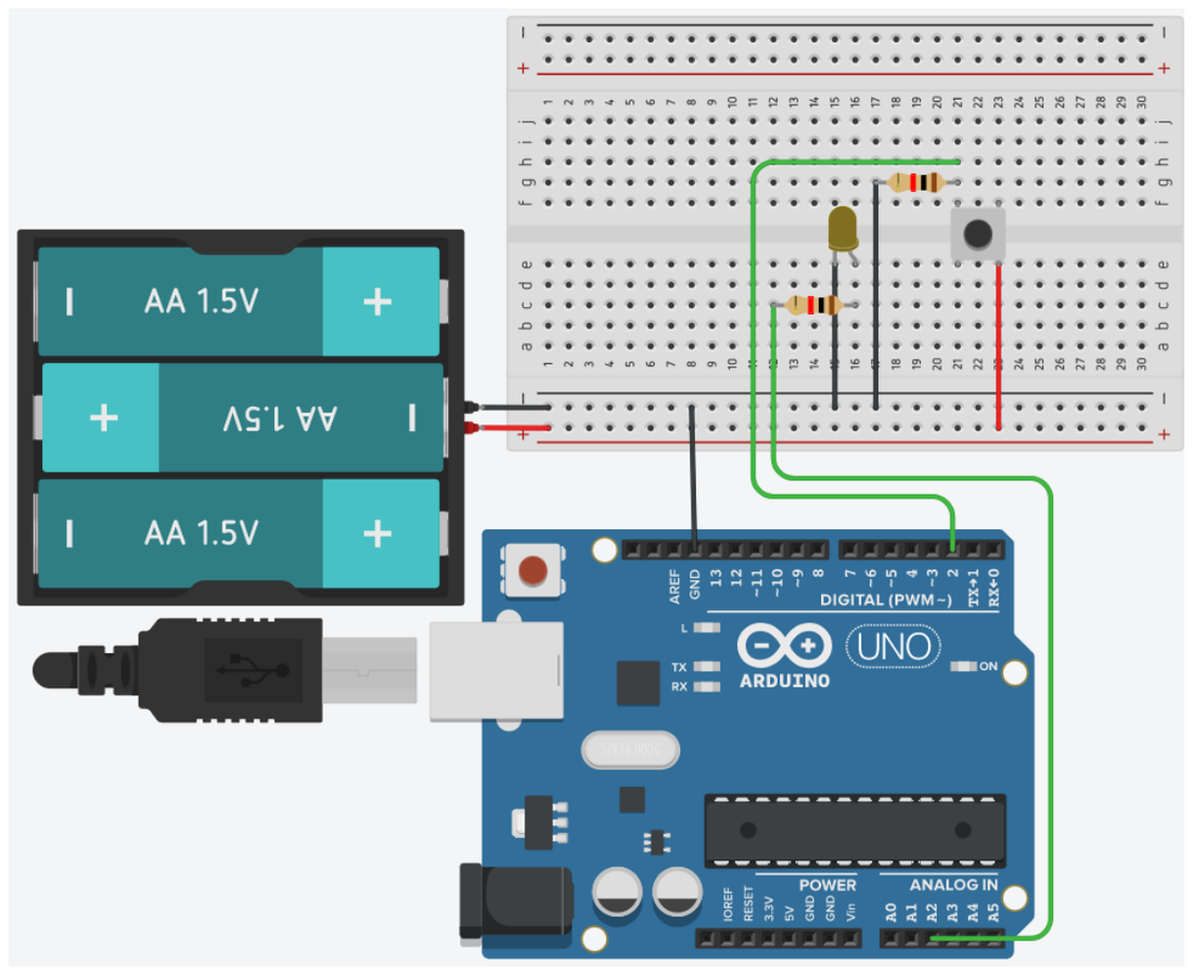
The difference between polling and interrupts is best understood when you see a press get lost. The circuit below has two counters shown in binary on LEDs: one updated by polling in a loop with long pauses, the other from an interrupt routine. Press the button rapidly and watch which one falls behind.
volatile tells the compiler that the
variable can change "behind its back", from an interrupt routine. Without it, the compiler is
allowed to read the variable once and keep using the copy in a register - and the loop would
never notice the presses.13Work tasks
- Build the circuit with a button on pin 2 and an LED on pin 13.
- Implement counting presses by polling, with
delay(200)in the loop. Press rapidly and observe how many presses are lost. - Rewrite the program using interrupts and repeat the test - compare the results.
- Remove the word
volatileand compile with optimizations; observe whether the program hangs. - Add bounce filtering inside the ISR and check that each physical press produces exactly one increment.
- Configure the second button on INT1 (pin 3) so that it resets the counter.
- Change the trigger type from
FALLINGtoCHANGEand explain why the counter increases twice as fast. - Measure the interrupt latency with the program above and compare it with the polling latency.
14Extended application
CHANGE, and determine
both the number of steps and the direction of rotation, by comparing the state of the
two signals at the moment of the edge. Print the position over serial and light a different LED
for each direction.
Hint: when rotating clockwise, signal A leads signal B by 90°; rotating the other way, the relationship reverses.