Digital ports are the microcontroller's interface with the outside world. Each port is controlled by exactly three registers, and understanding their role explains everything that happens at the pin level: from lighting an LED to reading a button with no external components.
1Lab objectives
- Understanding the role of the
DDRx,PORTxandPINxregisters - Configuring pins through direct register access, with bitwise operations
- Using the internal pull-up resistors to read buttons
- Implementing contact-bounce removal
- Comparing the speed of
digitalWrite()with a direct register write
2Materials needed
- 1 Arduino Uno
- 1 Breadboard
- 4 LEDs
- 4 220 Ω resistors
- 2 Buttons
- 10 Jumper wires
3The three registers of a port
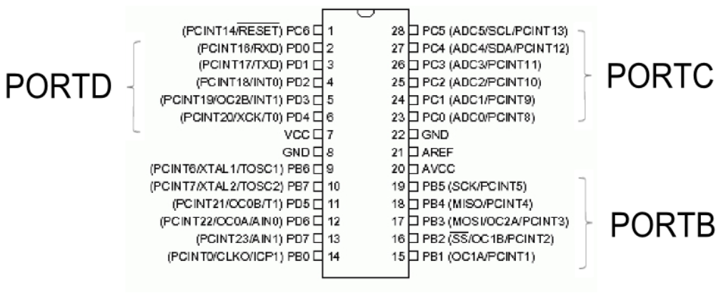
The ATmega328P has three ports: B (digital pins 8-13), C (analog pins A0-A5) and D (digital pins 0-7). Each is controlled by three 8-bit registers:
| Register | Full name | Role | Access |
|---|---|---|---|
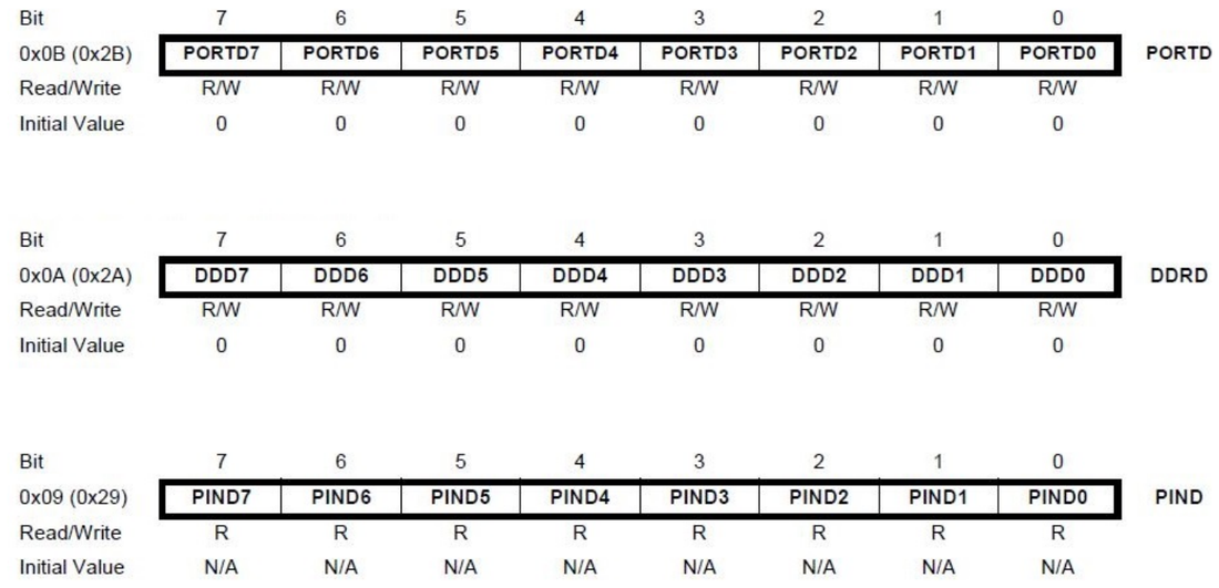
DDRx | Data Direction Register | sets the direction: 0 = input, 1 = output | read / write |
PORTx | Data Register | on output: the logic level on input: enables the internal pull-up | read / write |
PINx | Port Input Pins | reflects the real state of the pins | read only |
The complete configuration table
| DDRxn | PORTxn | Configuration | Equivalent resistance | Use |
|---|---|---|---|---|
| 0 | 0 | input, floating | very high (high Z) | to avoid - random readings |
| 0 | 1 | input with pull-up | 20-50 kΩ to 5 V | reading buttons, with no external components |
| 1 | 0 | output LOW | ~25 Ω to GND | turn off the LED / pull the load to ground |
| 1 | 1 | output HIGH | ~25 Ω to 5 V | turn on the LED |
4Internal structure of a pin
5Register simulator
Click on bits to change the registers. The state of the pins at the bottom updates exactly per the configuration table - just like on the real microcontroller.
6Mask lab
You never modify the whole register if you want to change a single pin - that would affect the other seven. Bit masks are used, built with the shift operator:
| Operation | Syntax | Effect |
|---|---|---|
| Set bit (1) | PORTB |= (1 << PB5); | only bit 5 becomes 1 |
| Clear bit (0) | PORTB &= ~(1 << PB5); | only bit 5 becomes 0 |
| Toggle | PORTB ^= (1 << PB5); | bit 5 flips its state |
| Test bit | if (PINB & (1 << PB0)) | true if bit 0 is 1 |
| Set a group | DDRB |= 0b00001111; | pins 8-11 become outputs |
Check below, bit by bit, what each operation does. Choose the
& operator with operand B set to 11011111 to see how bit 5 gets
cleared exactly.
~(1 << n) works
1 << 5 produces 00100000. Negation gives 11011111 -
every bit at 1, except the one at position 5. AND with this mask leaves every other bit
untouched and forces only the desired bit to 0.7Wiring diagrams
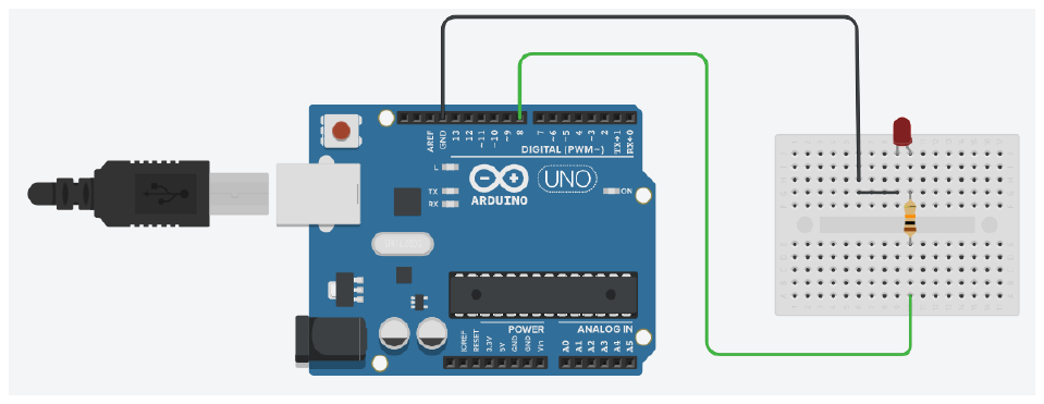
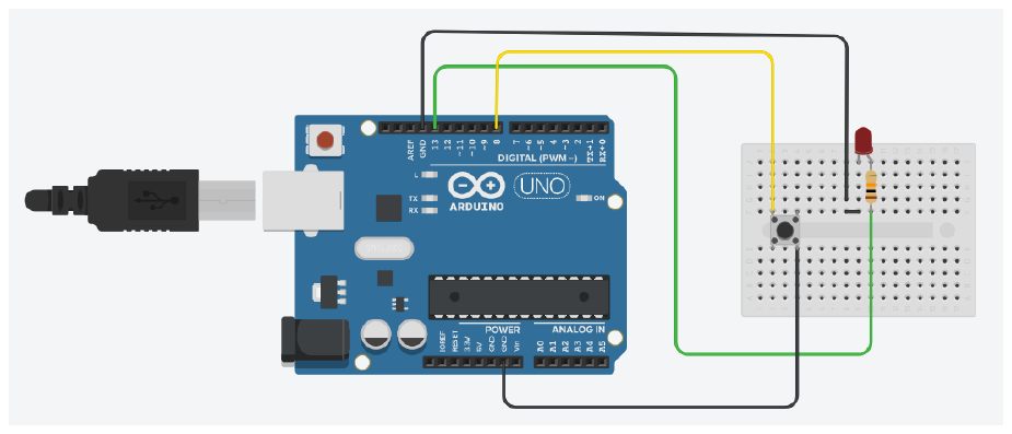

PORTD = 0b00000001, with DDRD having bit 0 at 0 (input).
Fig. 2.7 in the handout8Contact bounce
A mechanical button does not switch cleanly. The metal contacts bounce for a few milliseconds on touch, generating dozens of false transitions. Without filtering, a single physical press is seen by the program as several presses.
9Debounce simulator
Follow, step by step, how the algorithm rejects false transitions and only
accepts the stable state. Notice that the bounces at t = 102 and t = 107
produce no increment at all.
10Source code
Arduino functions vs. direct register access
void setup() {
  // --- Arduino variant: readable, but slow ---
  pinMode(13, OUTPUT);
  pinMode(2, INPUT_PULLUP);

  // --- equivalent register variant: fast ---
  DDRB  |= (1 << PB5);    // pin 13 = output
  DDRD  &= ~(1 << PD2);   // pin 2  = input
  PORTD |= (1 << PD2);    // enable pull-up on pin 2
}

void loop() {
  // reading the button: 0 = pressed, because of the pull-up
  if (!(PIND & (1 << PD2))) {
    PORTB |= (1 << PB5);    // turn on
  } else {
    PORTB &= ~(1 << PB5);   // turn off
  }
}
digitalWrite() needs
about 50 clock cycles: it checks the pin is valid, looks up the port in a Flash table,
and disables PWM if it was active. PORTB |= (1 << PB5) compiles into a
single instruction. At 16 MHz, the difference is between about 3 µs and 62 ns - roughly
a factor of 50.Measuring the speed difference
We do not have the serial monitor yet (lab 6), so we do not print the duration: we make it visible. Each method toggles the pin in a tight loop, and the pin drives a separate LED. The faster the method, the sooner the loop finishes and the shorter the "busy" LED stays lit. The difference is visible to the naked eye, and it can also be measured on an oscilloscope.
const uint16_t N = 20000;

void setup() {
  DDRB |= (1 << PB0);          // pin 8: the pin being toggled
  DDRB |= (1 << PB4);          // pin 12: marker "running digitalWrite"
  DDRB |= (1 << PB3);          // pin 11: marker "running the register variant"
}

void loop() {
  // ---- function-call variant: the marker on pin 12 stays lit as long as it runs
  PORTB |= (1 << PB4);
  for (uint16_t i = 0; i < N; i++) {
    digitalWrite(8, HIGH);
    digitalWrite(8, LOW);
  }
  PORTB &= ~(1 << PB4);

  delay(400);

  // ---- register variant: the marker on pin 11
  PORTB |= (1 << PB3);
  for (uint16_t i = 0; i < N; i++) {
    PORTB |=  (1 << PB0);
    PORTB &= ~(1 << PB0);
  }
  PORTB &= ~(1 << PB3);

  delay(400);
}
digitalWrite variant
stays visibly lit - tens of milliseconds. The marker for the register variant blinks so briefly
it is barely noticeable. The ratio between the two durations is exactly the factor of about 50
from the box above.Complete debounce
const uint8_t BUTTON_PIN = 2;
const uint8_t LED_PIN   = 13;
const uint16_t DEBOUNCE_INTERVAL = 40;   // ms

bool ledState       = false;
bool lastReading    = HIGH;
bool stableState    = HIGH;
unsigned long lastChangeTime = 0;

void setup() {
  pinMode(BUTTON_PIN, INPUT_PULLUP);
  pinMode(LED_PIN, OUTPUT);
}

void loop() {
  bool reading = digitalRead(BUTTON_PIN);

  if (reading != lastReading) {          // any change restarts the timer
    lastChangeTime = millis();
    lastReading  = reading;
  }

  if (millis() - lastChangeTime > DEBOUNCE_INTERVAL) {
    if (reading != stableState) {        // the state has stabilized
      stableState = reading;

      if (stableState == LOW) {          // falling edge = a real press
        ledState = !ledState;
        digitalWrite(LED_PIN, ledState);   // a single toggle per press
      }
    }
  }
}
A light effect on four LEDs
void setup() {
  DDRB |= 0b00001111;    // pins 8, 9, 10, 11 as outputs, in a single operation
}

void loop() {
  // shift left
  for (uint8_t i = 0; i < 4; i++) {
    PORTB = (PORTB & 0xF0) | (1 << i);   // keep bits 4-7, set only one of bits 0-3
    delay(120);
  }
  // shift right, without repeating the ends
  for (int8_t i = 2; i > 0; i--) {
    PORTB = (PORTB & 0xF0) | (1 << i);
    delay(120);
  }
}
(PORTB & 0xF0)The mask leaves bits 4-7 untouched
(including D13, the onboard LED) and lets only bits 0-3 be rewritten. Without it, a direct
assignment would turn off everything on the port's other pins.11Interactive circuit
An input pin is read from PINx, not from PORTx - and when you use the internal pull-up resistor, the logic is inverted: a pressed button means 0. The circuits below let you press the button with your mouse and watch the bit in PIND change in real time.
PORTD |= (1 << PD2); - without the pull-up resistor, the input is left
"floating" and the reading becomes unpredictable.if (0), that is always false,
so its body never runs. There are four lines to complete, marked in the code. The point of the
whole exercise: we do not care whether the button is pressed, but the moment it was
pressed. This is called a falling edge and it is caught by comparing the current reading
with the one from the previous pass of the loop - which is why we need the
previousState variable and step 4, which keeps it up to date. Without the 20 ms
from step 3, a single click can be seen as dozens of presses, because the contacts bounce for a
few milliseconds. Check it on the oscilloscope: the LED must toggle exactly once for every
press. If you get stuck, the 💡 view solution button loads a correct variant into the
editor.12Work tasks
- Wire up 4 LEDs on pins 8-11 and light them sequentially, using only register operations.
- Connect a button on pin 2 with the internal pull-up; print its idle and pressed value over serial.
- Check what is read on an input pin left floating, with no pull-up.
- Implement software debounce and count presses; check that each physical press produces exactly one increment.
- Modify the program so each press reverses the direction of the light effect.
- Run the benchmark and note the ratio between
digitalWrite()and direct access. - Build a 4-bit binary counter on the LEDs, incremented on each button press.
- Try
PORTB = 0b00000001;with no mask and observe what happens to the LED on D13.
13Extended application
randomSeed(millis());
Further extension: detect a long press (over 1 second) and use it to reset a roll counter, also shown in binary on the LEDs.