This preparatory session fixes the one technique without which the rest of the
semester makes no sense: manipulating individual bits of a register. Library functions such as
digitalWrite() exist only on Arduino; bit masks work identically on AVR, STM32,
ESP32, PIC, or any other microcontroller in the world.
1Lab objectives
- Quick conversion between binary, hexadecimal and decimal
- Correct use of the six bitwise operators
- Building masks with the shift operator
- Applying the four fundamental idioms: set, clear, toggle, test
- Writing and reading multi-bit fields
- Understanding the nature of read-modify-write and atomicity issues
- Writing portable code, independent of the Arduino library
2Why we work directly on registers
A microcontroller is configured exclusively by writing values into registers - special memory locations wired directly to hardware. Each bit of a register controls a concrete function: a pin's direction, enabling a peripheral, choosing a prescaler.
| Aspect | Library function | Direct register access |
|---|---|---|
| Speed | ~50 cycles (about 3 µs at 16 MHz) | 1 cycle (62.5 ns) |
| Flash memory used | hundreds of bytes of helper code | one instruction |
| Portability | only where the library exists | anywhere, with different register names |
| Control | only what the library author provided | everything the hardware allows |
| Readability | very good for beginners | requires the documentation (datasheet) |
| Debugging | hides what is happening | direct correspondence with the datasheet |
3Numbering systems
An 8-bit register is naturally written in binary, but binary is hard to read. Hexadecimal is the standard compromise: each hexadecimal digit corresponds to exactly 4 bits.
| Binary | Hex | Decimal | Binary | Hex | Decimal |
|---|---|---|---|---|---|
| 0000 | 0 | 0 | 1000 | 8 | 8 |
| 0001 | 1 | 1 | 1001 | 9 | 9 |
| 0010 | 2 | 2 | 1010 | A | 10 |
| 0011 | 3 | 3 | 1011 | B | 11 |
| 0100 | 4 | 4 | 1100 | C | 12 |
| 0101 | 5 | 5 | 1101 | D | 13 |
| 0110 | 6 | 6 | 1110 | E | 14 |
| 0111 | 7 | 7 | 1111 | F | 15 |
0b10110100      // binary  - every bit is visible
0xB4            // hex     - compact: B=1011, 4=0100
180             // decimal - says nothing about the bits

// all three are IDENTICAL to the compiler
1011 0100 → B and 4 → 0xB4. The reverse is
just as simple. With practice, the conversion becomes instant - and you will need it on every
page of a datasheet.| Bit position | 7 | 6 | 5 | 4 | 3 | 2 | 1 | 0 |
|---|---|---|---|---|---|---|---|---|
| Decimal value | 128 | 64 | 32 | 16 | 8 | 4 | 2 | 1 |
1 << n | 0x80 | 0x40 | 0x20 | 0x10 | 0x08 | 0x04 | 0x02 | 0x01 |
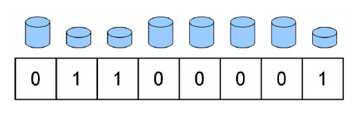
0b01100001 = 0x61 = 97.
Fig. 2.3 in the handout4Bitwise operators
| Operator | Name | Rule | Used for |
|---|---|---|---|
& | AND | 1 only if both bits are 1 | testing and clearing bits |
| | OR | 1 if at least one bit is 1 | setting bits |
^ | exclusive OR | 1 if the bits differ | toggling bits |
~ | negation | inverts every bit | building clearing masks |
<< | left shift | moves bits left, fills with 0 | positioning the mask |
>> | right shift | moves bits right | extracting fields |
Truth tables
| A | B | A & B | A | B | A ^ B | ~A |
|---|---|---|---|---|---|
| 0 | 0 | 0 | 0 | 0 | 1 |
| 0 | 1 | 0 | 1 | 1 | 1 |
| 1 | 0 | 0 | 1 | 1 | 0 |
| 1 | 1 | 1 | 1 | 0 | 0 |
1 & 2 gives 0 - the bits
do not overlap (01 and 10). But 1 && 2 gives 1 - both values are
nonzero, so true. The same trap exists between | and ||. The
confusion produces bugs that compile with no warning at all.The properties that make everything work
| Property | Practical consequence |
|---|---|
x | 0 = x | OR with 0 leaves the bit unchanged → bits set to 0 in the mask stay untouched |
x | 1 = 1 | OR with 1 forces it to 1 → bits set to 1 in the mask get set |
x & 1 = x | AND with 1 leaves the bit unchanged → bits set to 1 in the mask stay untouched |
x & 0 = 0 | AND with 0 forces it to 0 → bits set to 0 in the mask get cleared |
x ^ 0 = x | XOR with 0 leaves the bit unchanged |
x ^ 1 = ~x | XOR with 1 inverts the bit |
5Operator playground
Toggle bits directly on the binary representation and watch how the result forms, position by position. Experimentally verify every property from the table above.
6Building masks
A mask is a value in which the bits we care about are marked with 1. It is built with the shift operator, starting from the value 1:
1                 ->  0000 0001     (bit 0)
1 << 1            ->  0000 0010     (bit 1)
1 << 2            ->  0000 0100     (bit 2)
1 << 5            ->  0010 0000     (bit 5)
1 << 7            ->  1000 0000     (bit 7)

~(1 << 5)         ->  1101 1111     (every bit 1, except bit 5)

(1 << 3) | (1 << 1)  ->  0000 1010  (bits 3 AND 1 at once)
PORTB |= 0b00100000; works, but you have to count positions every time.
PORTB |= (1 << PB5); explicitly says which bit, using the name from the
datasheet. The compiler produces exactly the same machine code - the shift is computed at
compile time, not at run time.1 is a 16-bit
int. For 8-bit registers it does not matter, but for bit 31 of a 32-bit register
(STM32, ESP32) you must write 1UL << 31, otherwise the result is undefined.7Mask simulator
Choose an operation and a bit position, then press "apply". Watch the generated mask, the corresponding expression, and the bit that changes - highlighted in orange. Notice that the rest of the bits always stay untouched.
0b00001010. Set bit
5, then clear bit 1, then toggle bit 3 twice. Check every time that the uninvolved bits kept
their value - that is the entire point of masks.8The four fundamental idioms
Practically all embedded code in the world uses these four forms. They are worth memorizing as such:
| Operation | Idiom | Why it works |
|---|---|---|
| Set (make it 1) | REG |= (1 << n); | OR with 1 forces 1; OR with 0 changes nothing |
| Clear (make it 0) | REG &= ~(1 << n); | AND with 0 forces 0; AND with 1 changes nothing |
| Toggle | REG ^= (1 << n); | XOR with 1 inverts it; XOR with 0 changes nothing |
| Test | if (REG & (1 << n)) | AND isolates the bit; nonzero result if the bit is 1 |
#define BIT(n)              (1UL << (n))

#define SET_BIT(reg, n)     ((reg) |=  BIT(n))
#define CLR_BIT(reg, n)     ((reg) &= ~BIT(n))
#define TGL_BIT(reg, n)     ((reg) ^=  BIT(n))
#define CHK_BIT(reg, n)     (((reg) &  BIT(n)) != 0)

// writes a value of 0 or 1 into a bit, with no branch
#define WRT_BIT(reg, n, v)  ((reg) = ((reg) & ~BIT(n)) | ((v) ? BIT(n) : 0))

// usage examples
SET_BIT(DDRB,  PB5);        // pin 13 becomes an output
SET_BIT(PORTB, PB5);        // pin 13 to HIGH
CLR_BIT(PORTB, PB5);        // pin 13 to LOW
TGL_BIT(PORTB, PB5);        // toggle pin 13

if (CHK_BIT(PIND, PD2)) {   // the button is NOT pressed (pull-up)
    // ...
}
SET_BIT(x, a + 1) would expand incorrectly,
because of operator precedence. This is a classic source of bugs that are very hard to spot.9Multi-bit fields
Many settings do not take up a single bit, but a group. For example, a timer's prescaler is
given by three bits CS12:CS10, and the ADC channel by four bits
MUX3:MUX0.
// Say bits 3, 4, 5 of port B form a 3-bit "field" (a value from 0 to 7
// sent to an external circuit), while bits 0, 1, 2 control something
// completely different and must NOT be touched.

// WRONG: wipes out the rest of the register
PORTB = 0b00101000;                    // the field is 5... but bits 0-2 are lost!

// CORRECT: clear only the field, then write the value
PORTB &= ~((1 << PB5) | (1 << PB4) | (1 << PB3));   // 1. clear the field
PORTB |=  (1 << PB5);                                 // 2. write the new value

// General form, with mask and shift
#define FIELD_SET(reg, mask, shift, val) \
    ((reg) = ((reg) & ~((mask) << (shift))) | (((val) & (mask)) << (shift)))

// example: write the value 5 into the 3-bit field starting at position 3
FIELD_SET(PORTB, 0x07, 3, 5);
Reading a field
// Isolate the field with AND, then bring it to position 0 by shifting
uint8_t lowerHalf   = (PORTB & 0x0F);          // bits 0-3, already at position 0

// a field that does NOT start at position 0: shift first, mask after
uint8_t threeBitField = (PORTB >> 3) & 0x07;     // bits 3-5

uint8_t topBit       = (PORTB >> 5) & 0x01;     // a single bit, position 5

#define FIELD_GET(reg, mask, shift)  (((reg) >> (shift)) & (mask))
10Read-modify-write
The expression PORTB |= (1 << PB5); looks like a single operation, but the
processor executes it in three steps:
PORTB |= (1 << PB5);

; translates into:
    in   r24, 0x05      ; 1. READ PORTB into register r24
    ori  r24, 0x20      ; 2. MODIFY: OR with mask 0b00100000
    out  0x05, r24      ; 3. WRITE r24 back into PORTB
PORTB, PORTD, DDRB) and for a
constant single-bit mask, the compiler uses the sbi / cbi
instructions, which are atomic and take a single cycle. For registers in extended memory
(TCCR1B, ADCSRA, UCSR0B) or for masks computed at run
time, the full three-instruction sequence is generated.11Atomicity
An operation is atomic if it cannot be interrupted halfway through. The problem shows up when the same register or the same variable is modified both from the main program and from an interrupt routine.
| Situation | Atomic? | Solution |
|---|---|---|
PORTB |= (1 << PB5); - constant mask, low I/O register | yes (sbi) | nothing to do |
TCCR1B |= (1 << CS12); - extended register | no | critical section, if the ISR touches the same register |
Reading a uint16_t modified in an ISR | no | critical section required |
counter++ on a volatile uint8_t | no | critical section |
Reading a volatile uint8_t | yes | just volatile |
// WRONG: re-enables interrupts even if the caller had them disabled
cli();
value = counter;
sei();                      // <-- assumes they were enabled. Not guaranteed!

// CORRECT: save and restore the exact prior state
uint8_t sreg = SREG;         // SREG holds the I bit (Global Interrupt Enable)
cli();
value = counter;             // critical section: nothing can interrupt it
SREG = sreg;                 // restores EXACTLY the previous state

// BEST: macro from the standard AVR library
#include <util/atomic.h>

ATOMIC_BLOCK(ATOMIC_RESTORESTATE) {
    value = counter;         // saving and restoring happen automatically
}
volatile is enough. For more complex structures you can use the
"double read" technique: read the variable twice and accept the result only if the two reads
agree.12Simulator: corrupting an RMW operation
Watch exactly how an interrupt occurring between the read and the write makes its own change vanish without a trace. This is one of the hardest bugs to spot in embedded programming, because it appears rarely and seemingly at random.
loop()
and from an ISR, every RMW operation in the main program must be protected with
ATOMIC_BLOCK. Alternatively - and preferably - set the rule that each register is
modified from a single place.13Memory-mapped registers
The name PORTB is not an ordinary variable: it is a macro that points to a
physical address in the memory space, wired directly to hardware.
// In the AVR header files:
#define PORTB   (*(volatile uint8_t *)0x25)
//               │  │                  └── the register's physical address
//               │  └── cast to a pointer to a volatile byte
//               └── dereference: we work with the VALUE at that address

// So PORTB |= 0x20;  means:
*(volatile uint8_t *)0x25 |= 0x20;

// The same thing can be written explicitly:
volatile uint8_t *portb = (volatile uint8_t *)0x25;
*portb |= (1 << 5);
volatile is mandatory hereA register's value can
change without the program modifying it - for example PIND reflects the
physical state of the pins. Without volatile, the compiler would read the register
once and reuse the stored value, and the loop
while (!(UCSR0A & (1 << RXC0))); would never end.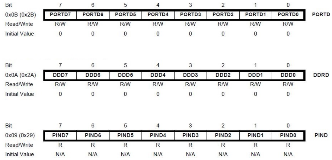
PIND is marked R - read only.
Fig. 2.4 in the handout(1 << DDD4).
Read/Write says whether you can write to it, and Initial Value the value after
reset. You will find this exact format for absolutely every register, in every lab that
follows.14Porting to other controllers
The bitwise idioms stay identical. Only the register names change, and sometimes the peripheral's architecture. Here is the same operation - "turn on an LED" - on four platforms:
// ---------- AVR / ATmega328P (Arduino Uno) ----------
DDRB  |= (1 << PB5);            // pin as output
PORTB |= (1 << PB5);            // pin to HIGH
PORTB &= ~(1 << PB5);           // pin to LOW

// ---------- STM32 (F1/F4 series, direct registers) ----------
RCC->APB2ENR |= (1 << 3);       // enable port C's clock
GPIOC->CRH   |= (1 << 20);      // configure pin 13 as output
GPIOC->BSRR   = (1 << 13);      // pin to HIGH  (dedicated register, ATOMIC)
GPIOC->BSRR   = (1 << 29);      // pin to LOW   (bit 13 + 16)

// ---------- ESP32 ----------
GPIO.enable_w1ts   = (1 << 2);  // pin as output
GPIO.out_w1ts      = (1 << 2);  // pin to HIGH  (write-1-to-set, ATOMIC)
GPIO.out_w1tc      = (1 << 2);  // pin to LOW   (write-1-to-clear)

// ---------- PIC (16F series) ----------
TRISB &= ~(1 << 5);             // pin as output (0 = output on PIC!)
LATB  |=  (1 << 5);             // pin to HIGH
LATB  &= ~(1 << 5);             // pin to LOW
| Aspect | AVR | STM32 | ESP32 | PIC |
|---|---|---|---|---|
| Register width | 8 bits | 32 bits | 32 bits | 8 bits |
| Pin direction | DDRx, 1 = output | MODER / CRL | enable | TRISx, 0 = output |
| Writing a level | PORTx | ODR or BSRR | out | LATx |
| Reading a pin | PINx | IDR | in | PORTx |
| Atomic set | sbi (automatic) | BSRR | w1ts/w1tc | - |
| Peripheral clock | always on | must be enabled (RCC) | managed by the SDK | always on |
BSRR on STM32, w1ts/w1tc
on ESP32). Writing to them is a single operation, so it is atomic by construction - the
problem from section 11 disappears completely. The existence of these registers is proof that
the RMW problem is real and important enough for manufacturers to add special hardware for it.TRISx uses the opposite
convention from AVR: 0 means output, 1 means input. Code ported mechanically works exactly
backward. Always check the convention in the datasheet, never assume it.15Source code
Binary display of a value
// Connect 6 LEDs to pins 8...13, that is, to bits 0...5 of port B.
// The LED bar becomes the "binary display" of any 6-bit value.

void show(uint8_t v) {
  PORTB = v & 0x3F;     // bits 0-5 of the value reach the 6 LEDs
  _delay_ms(1500);      // pause, so you have time to read the bar
}

int main(void) {
  DDRB = 0x3F;                    // all 6 pins, outputs

  uint8_t reg = 0b00001010;
  show(reg);                      // initial: 001010

  reg |=  (1 << 5);   show(reg);  // set b5: 101010
  reg &= ~(1 << 1);   show(reg);  // clr b1: 101000
  reg ^=  (1 << 3);   show(reg);  // tgl b3: 100000

  // TESTING a bit: the LED on pin 7 shows the answer
  DDRD |= (1 << PD7);
  if (reg & (1 << 5)) PORTD |=  (1 << PD7);   // bit 5 is SET
  else                PORTD &= ~(1 << PD7);   // bit 5 is clear

  while (1) { }
}
Manipulation exercises
// 1. Counting the set bits (Kernighan's algorithm)
uint8_t countBits(uint8_t v) {
  uint8_t n = 0;
  while (v) {
    v &= (v - 1);            // clear the rightmost set bit
    n++;
  }
  return n;
}

// 2. Testing whether a value is a power of 2
bool isPowerOf2(uint8_t v) {
  return v && !(v & (v - 1));
}

// 3. Reversing the order of the bits
uint8_t reverseBits(uint8_t v) {
  uint8_t r = 0;
  for (uint8_t i = 0; i < 8; i++) {
    r = (r << 1) | (v & 1);
    v >>= 1;
  }
  return r;
}

// 4. Swapping two values with no temporary variable
void swap(uint8_t *a, uint8_t *b) {
  *a ^= *b;  *b ^= *a;  *a ^= *b;
}

// 5. Extracting the upper and lower nibble
uint8_t nibbleHigh(uint8_t v)  { return (v >> 4) & 0x0F; }
uint8_t nibbleLow(uint8_t v)   { return  v       & 0x0F; }
The same application, three levels of abstraction
// ============ LEVEL 1: the Arduino library ============
// advantage: readable right away   drawback: slow, not portable
void blinkArduino() {
  pinMode(13, OUTPUT);
  digitalWrite(13, HIGH);
  delay(500);
  digitalWrite(13, LOW);
  delay(500);
}

// ============ LEVEL 2: AVR registers, with names ============
// advantage: fast, explicit   drawback: tied to AVR
void blinkRegisters() {
  DDRB  |=  (1 << PB5);
  PORTB |=  (1 << PB5);
  _delay_ms(500);
  PORTB &= ~(1 << PB5);
  _delay_ms(500);
}

// ============ LEVEL 3: your own abstraction layer ============
// advantage: fast AND portable - only this block changes when porting
#if defined(__AVR__)
  #define LED_DIR_REG   DDRB
  #define LED_OUT_REG   PORTB
  #define LED_PIN_NR    PB5
#elif defined(ESP32)
  #define LED_DIR_REG   GPIO.enable
  #define LED_OUT_REG   GPIO.out
  #define LED_PIN_NR    2
#endif

#define LED_INIT()    (LED_DIR_REG |=  (1UL << LED_PIN_NR))
#define LED_ON()      (LED_OUT_REG |=  (1UL << LED_PIN_NR))
#define LED_OFF()     (LED_OUT_REG &= ~(1UL << LED_PIN_NR))
#define LED_TOGGLE()  (LED_OUT_REG ^=  (1UL << LED_PIN_NR))

void blinkPortable() {
  LED_INIT();
  LED_ON();     _delay_ms(500);
  LED_OFF();    _delay_ms(500);
}
LED_ON(), and porting to another microcontroller means
rewriting a single block of definitions. You will use this structure in the final project.Measuring the performance difference
// We do not have the serial monitor yet (lab 6), so we do not print the
// duration: we make it VISIBLE. Each method keeps a marker LED lit for
// as long as its loop runs. The faster the method, the shorter the
// marker blinks. On an oscilloscope, the pulse width IS the measured duration.

#define N 20000

int main(void) {
  DDRB |= (1 << PB0);                             // the pin being toggled
  DDRD |= (1 << PD5) | (1 << PD6) | (1 << PD7);   // the three markers

  uint16_t i;
  while (1) {
    PORTD |= (1 << PD7);                          // function-call variant
    for (i = 0; i < N; i++) { digitalWrite(8, HIGH); digitalWrite(8, LOW); }
    PORTD &= ~(1 << PD7);
    _delay_ms(300);

    PORTD |= (1 << PD6);                          // register variant
    for (i = 0; i < N; i++) { PORTB |= (1 << PB0); PORTB &= ~(1 << PB0); }
    PORTD &= ~(1 << PD6);
    _delay_ms(300);

    PORTD |= (1 << PD5);                          // toggling by writing to PINB
    for (i = 0; i < N; i++) { PINB = (1 << PB0); PINB = (1 << PB0); }
    PORTD &= ~(1 << PD5);
    _delay_ms(300);
  }
}
PINx register
toggles the corresponding bit of PORTx. This is the fastest way to toggle a
pin - a single, atomic instruction. A detail found only in the datasheet, never in an Arduino
tutorial.16Interactive circuit
Here you see, at the same time, the three faces of the same thing: the C instruction you write, the bit that changes in the register, and the LED that lights up. The register panel is also interactive - click directly on a bit to toggle it manually and watch what happens to the circuit.
<< moves that bit - which is why the effect comes from a single line.17Work tasks
- Convert by hand, with no calculator:
0b11010110to hex and decimal;0x3Fto binary. - Implement the binary display function and check it for 0, 1, 128 and 255.
- Write the four macros (SET, CLR, TGL, CHK) and use them to drive an LED.
- Set bits 1, 3 and 5 of a variable at the same time, with a single expression.
- Clear a 3-bit field and write the value 5 into it, without affecting the rest of the register.
- Extract the upper and lower nibble of a byte and display them separately.
- Implement counting the set bits and check the result for
0b10110110. - Run the benchmark and note the ratio between the three methods of toggling a pin.
- Write the same blink program at the three levels of abstraction and compare the size of the compiled code.
- Look up the address of the
PORTDregister in the ATmega328P datasheet and access it through a pointer, without using its name.
18Extended application
pinInit(port, bit, dir), pinWrite(port, bit, val),
pinRead(port, bit) and pinToggle(port, bit), using exclusively
bitwise operations and pointers to registers.
Requirements: it must work on all three ports (B, C, D), be at least 10 times faster than
digitalWrite(), and use no function from the Arduino library. Compare the
size of the compiled code with the variant that uses the standard library.
Extension: add a
pinToggleAtomic() variant that uses the PINx
trick, and demonstrate, with a logic analyzer or a second pin, that it is atomic.