The first session sets the foundations: what a program that runs forever on a microcontroller looks like, what resources the ATmega328P actually has, what each pin of the board does, and how the first digital output is driven.
1Lab objectives
- Installing the Arduino IDE and configuring the board and the upload port
- Understanding the
setup()/loop()structure and why it exists - Identifying the functions of each pin on the Arduino Uno board
- Choosing data types suited to a system with 2 KB of RAM
- Driving an output pin and checking that it works with an LED
2Materials needed
- 1 Arduino Uno board (ATmega328P)
- 1 Type B USB cable
- 1 Breadboard
- 1 5 mm LED
- 1 220 Ω resistor
- 2 Jumper wires
3Board architecture
The Arduino Uno board is built around the ATmega328P microcontroller, an 8-bit processor with a modified Harvard architecture. Its resources are modest - and that is exactly why every programming decision matters.
| Resource | Value | Notes |
|---|---|---|
| Clock frequency | 16 MHz | external crystal; one cycle lasts 62.5 ns |
| Flash memory (program) | 32 KB | of which 0.5 KB is taken by the bootloader |
| SRAM memory (data) | 2 KB | this is where variables live - the most critical resource |
| EEPROM memory | 1 KB | keeps data after power is removed |
| Digital pins | 14 (of which 6 have PWM) | D0–D13 |
| Analog inputs | 6 | A0–A5, 10-bit converter |
| Maximum current per pin | 40 mA | absolute maximum; keep under 20 mA |
| Total current across all pins | 200 mA | the microcontroller's limit |
int does not fit at all. On microcontrollers,
choosing a data type is not a matter of style, but of whether the program works at all.4Pin explorer
Click any pin to see its functions. Notice that many pins have multiple functions - for example D13 is at the same time the SPI clock and the onboard LED, while D0 and D1 are used by serial communication.
D0 and D1 are used
by Serial and by uploading the program. If you connect something to them, uploading
the sketch may fail. D13 already has an LED and a resistor mounted on the board, so
it is not ideal as an input.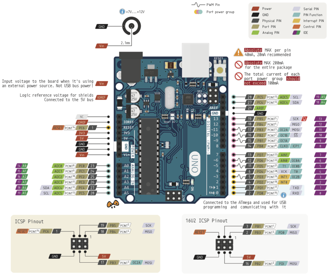
5Program structure
An ordinary program starts, does its job, and ends. A microcontroller program never ends: as long as the board is powered, the processor must be executing something. That is why the Arduino environment requires two functions:
| Function | When it runs | Typical role |
|---|---|---|
setup() | once, at power-up or after a reset | configuring pins, starting communication, initializing peripherals |
loop() | continuously, as soon as setup() finishes | reading sensors, making decisions, driving outputs |
/* The two functions you write in the sketch: */
void setup() { /* YOUR initialization code */ }
void loop()  { /* YOUR code, repeated forever */ }

/* ...and the Arduino environment adds this on its own, behind the scenes: */
int main(void)
{
    init();          // configures the timers and the ADC, called automatically

    setup();         // once, at power-up

    for (;;) {       // infinite loop
        loop();      // forever
    }
    return 0;        // never reached
}
loop(), the rest of the program never runs again. And if loop() is
empty, the processor still keeps running - drawing current for nothing.6Execution simulator
Follow, step by step, the real order of execution: setup() runs
once, then loop() repeats forever. Watch the value of the static counter, which
proves that the function really is being called repeatedly.
7Data types on AVR
| Type | Bytes | Range | When to use it |
|---|---|---|---|
bool | 1 | true / false | flags; it still takes a whole byte, not a bit |
char | 1 | −128 … 127 | ASCII characters |
uint8_t / byte | 1 | 0 … 255 | pin numbers, small counters, register values |
int | 2 | −32,768 … 32,767 | careful: on AVR it is 16 bits, not 32! |
unsigned int | 2 | 0 … 65,535 | ADC values, medium counters |
long | 4 | ±2.1 · 10⁹ | millis(), micros() |
float | 4 | ±3.4 · 10³⁸, ~7 digits | avoid: there is no hardware unit, calculations are slow |
int t = 1000 * 60; gives a wrong result, because 60,000 exceeds the range of a
16-bit int. Correct: long t = 1000L * 60; - the L suffix
forces the calculation onto 32 bits.float multiplication takes tens of times longer than an integer one and takes up
almost 1 KB of Flash just for the library. Wherever possible, work with scaled integers (for
example temperature in tenths of a degree, as an int).Important qualifiers
| Qualifier | Effect | When it is mandatory |
|---|---|---|
const | a value that does not change | pin numbers, thresholds |
static | keeps its value between calls | local counters inside loop() |
volatile | forbids optimizing away the access | any variable modified inside an ISR |
PROGMEM | stores the data in Flash, not in RAM | large constant tables, fixed text |
8Wiring diagram
9Source code
The minimal program - Blink
const uint8_t LED_PIN = 8;    // const + uint8_t: does not waste RAM

void setup() {
  pinMode(LED_PIN, OUTPUT);   // the pin becomes an output
}

void loop() {
  digitalWrite(LED_PIN, HIGH);  // turn on
  delay(500);                   // wait 500 ms
  digitalWrite(LED_PIN, LOW);   // turn off
  delay(500);
}
The same behavior, at the register level
The functions pinMode() and digitalWrite() exist only in the
Arduino environment. The same operations written directly on the registers work on any AVR
compiler and run about 50 times faster:
void setup() {
  DDRB |= (1 << PB0);           // pin 8 becomes an output  (same as pinMode(8, OUTPUT))
}

void loop() {
  PORTB |=  (1 << PB0);         // pin 8 to HIGH             (same as digitalWrite(8, HIGH))
  delay(500);
  PORTB &= ~(1 << PB0);         // pin 8 to LOW              (same as digitalWrite(8, LOW))
  delay(500);
}
| Operation | Arduino function | Register equivalent |
|---|---|---|
| Pin as output | pinMode(8, OUTPUT) | DDRB |= (1 << PB0); |
| Pin as input | pinMode(2, INPUT) | DDRD &= ~(1 << PD2); |
| Input with pull-up | pinMode(2, INPUT_PULLUP) | DDRD &= ~(1<<PD2); PORTD |= (1<<PD2); |
| Write HIGH | digitalWrite(8, HIGH) | PORTB |= (1 << PB0); |
| Write LOW | digitalWrite(8, LOW) | PORTB &= ~(1 << PB0); |
| Read pin | digitalRead(2) | (PIND & (1 << PD2)) |
(1 << PB0) is called
a bit mask and is the foundation of the whole course. If it is not yet clear why it
works, go through Laboratory 1B before moving on
to the next lab - it is explained there step by step, with an interactive simulator.Debugging without a screen: the LED as a tool
The microcontroller has no screen. Until the sixth lab, when you learn serial communication and can send text to the computer, the only debugging tool you have is the LED itself: you use it to show that the program has reached a certain point, or to "display" a small number, through counted blinks.
void setup() {
  pinMode(13, OUTPUT);
}

void loop() {
  static uint8_t counter = 0;    // static: keeps its value between calls
  counter++;

  // "display" the counter: one blink for each unit
  for (uint8_t i = 0; i < counter; i++) {
    digitalWrite(13, HIGH);
    delay(150);
    digitalWrite(13, LOW);
    delay(250);
  }

  delay(1500);                   // long pause = the "display" has finished
  if (counter >= 5) counter = 0;  // start over
}
loop() restarts, you see one more
blink: 1, 2, 3, 4, 5, then 1 again. This is proof that static really does keep the
value between calls - without it, the counter would return to 0 every time and you would always
see a single blink.Checking available memory
The sizes of the types are in the table in chapter 7. How much RAM is still free, however, can only be found out at run time, with the function below. Having no serial monitor yet, the program does not print the value, but signals it: if free memory drops below a threshold, the LED stays lit continuously.
// Returns the number of free bytes between the heap and the stack
int freeMemory() {
  extern int __heap_start, *__brkval;
  int v;
  return (int)&v - (__brkval == 0 ? (int)&__heap_start : (int)__brkval);
}

void setup() {
  pinMode(13, OUTPUT);
}

void loop() {
  if (freeMemory() < 256) {
    digitalWrite(13, HIGH);       // alarm: memory nearly exhausted
  } else {
    digitalWrite(13, LOW);
  }
  delay(500);
}
10Interactive circuit
The circuits below run the code right on the page, on a simulated ATmega328P. It is not an animation: PORTB really does drive the pin, the LED lights up because bit 5 became 1, and the 16 MHz clock runs just like on the real board. Press Start, then change the code and start again.
pinMode(13, OUTPUT) sets bit DDB5 to 1, and each digitalWrite
toggles bit PORTB5. The Arduino functions do nothing magic - they write into the same
registers you will use directly in the next lab. Try delay(100) and watch the
pulses bunch up on the oscilloscope.11Work tasks
- Install the Arduino IDE, select the Arduino Uno board and the correct serial port.
- Upload the Blink program and check that the onboard LED (D13) works.
- Wire up an external LED with a 220 Ω resistor on pin D8 and modify the program.
- Calculate the current through the LED and check that it stays under 20 mA.
- Change the timing so the LED is on for 100 ms and off for 900 ms.
- Run the size-checking program and note the values for
intandlong. - Experimentally verify the
int t = 1000 * 60;trap and fix it with theLsuffix. - Display the free RAM and watch how it drops after declaring an array of 200
int.
12Extended application
Reflection question: what data type is suited to the variable that holds the pause, and why would a
uint8_t not be enough?